
Configure and Test Dual-WAN Failover in pfSense
This guide prefers WAN1 and uses WAN2 when WAN1 fails. It covers one pfSense CE or pfSense Plus firewall with two working Internet connections. This is WAN failover, not failover between two firewall appliances. Gateway groups route new matching connections; existing sessions may need to reconnect when the public source address changes.
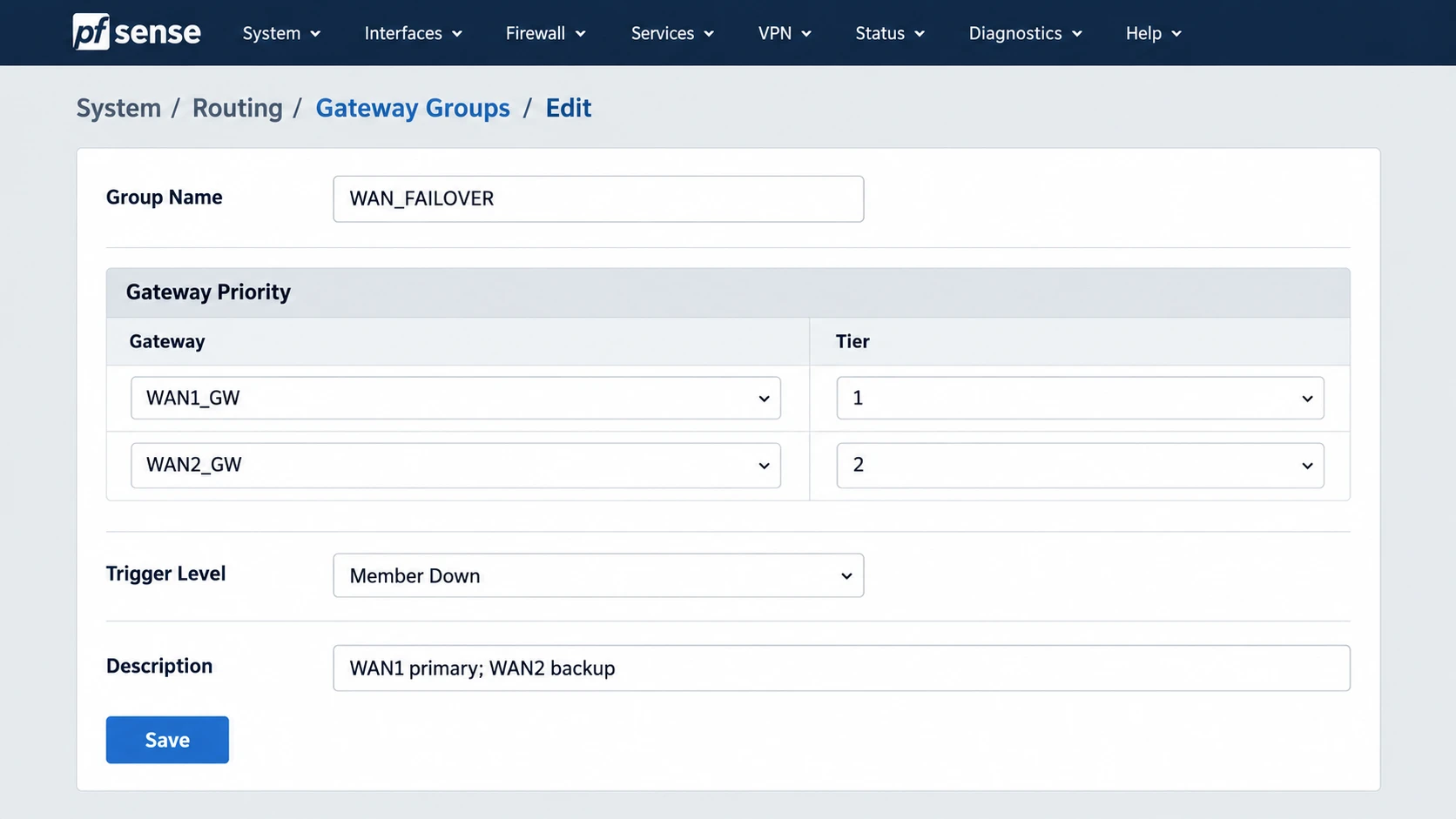
Illustration: A gateway group with WAN1 at Tier 1 and WAN2 at Tier 2. Choose the trigger level from the behavior your site needs.
Verify Both WANs Work Independently
BaselineConfirm WAN1 and WAN2 each have a usable IP address, gateway, and upstream path. If WAN2 is new, assign and enable it under Interfaces > Assignments, then set its provider’s address type. Check Status > Gateways and test outbound connectivity on each path before building failover. A gateway group cannot repair an unusable second circuit.
Interfaces > Assignments: WAN1 and WAN2 are assigned and enabledStatus > Gateways: both gateways Online with expected addressesDiagnostics > Ping: test an approved public endpoint via each WAN❯ What to Verify
Both Internet connections work on their own and the administratorcan still reach the firewall if either path changes.Choose Reliable Monitor Addresses
Health CheckUnder System > Routing > Gateways, inspect each gateway’s monitor IP and gateway monitoring settings. A monitor address must answer reliably through the intended WAN and represent reachability beyond a local modem when Internet failure detection is required. Use distinct, approved monitor targets for the two circuits. Do not disable monitoring: the group needs status to decide when a path failed.
System > Routing > Gateways > edit WAN1 and WAN2Confirm: monitor address, monitoring enabled, expected gateway IPStatus > Gateways: RTT/loss and Online state are sensible❯ What to Verify
Both gateways report a meaningful Online state and a WAN1 outagewill not leave its monitor reachable through only the local modem.Create a Tiered Failover Group
Gateway GroupOpen System > Routing > Gateway Groups. Create WAN_FAILOVER with WAN1 at Tier 1 and WAN2 at Tier 2. Select an approved trigger level, add a description, and save. Different tiers mean failover; putting both gateways at Tier 1 would load-balance connections instead.
System > Routing > Gateway Groups > AddName: WAN_FAILOVERWAN1 gateway: Tier 1WAN2 gateway: Tier 2Trigger Level: chosen from observed loss/latency requirements❯ What to Verify
The group lists WAN1 before WAN2 and Status > Gateways shows both members.Route Firewall and Client Traffic Correctly
Policy RoutingFor the firewall’s own traffic, set the IPv4 default gateway to the failover group in System > Routing > Gateways. For LAN client traffic, edit or add a LAN pass rule and choose WAN_FAILOVER in its advanced Gateway field. Place a rule for local and VPN destinations above that policy-routed rule with the Gateway left at default, so internal traffic follows the routing table. Apply changes and check rule order. Repeat for IPv6 only if both WANs and the policy are ready for it.
System > Routing > Gateways > Default Gateway: WAN_FAILOVER (IPv4)Firewall > Rules > LAN (top to bottom):1. Pass LAN -> local/VPN networks; Gateway: default2. Pass approved LAN -> Internet; Gateway: WAN_FAILOVER❯ What to Verify
Firewall-originated traffic has a failover default route, client Internettraffic matches the group, and local/VPN traffic is not sent toward a WAN.Establish a Before-Failure Baseline
ValidationFrom a LAN test client, open a new connection to an approved external IP-check service and record the observed public IP. Confirm it belongs to WAN1. Review Status > Gateways, the group members, DNS resolution, and a representative application. For multi-WAN, use new connections when comparing paths; existing states can preserve the old route.
Before failure: WAN1 Online, WAN2 OnlineNew client connection: public source address belongs to WAN1DNS and a representative application succeed❯ What to Verify
The preferred path is proven before any outage simulation.Simulate and Observe Failover
Controlled TestDuring the approved test, disconnect WAN1 at a point that actually makes its monitor fail. Watch Status > Gateways move WAN1 to a failed state, then start a fresh client connection and verify its public IP belongs to WAN2. Test DNS and the application again. If WAN1 remains Online, the monitor is still reachable; fix the monitor design before claiming the failover works. A live call or VPN may reconnect because its source address changed.
Expected after WAN1 failure:Status > Gateways: WAN1 down, WAN2 OnlineNew client connection: public source address belongs to WAN2DNS and approved application remain usable❯ What to Verify
The measured failover time and any interrupted sessions are recorded.Restore WAN1 and Record the Result
CloseoutReconnect WAN1 and wait for its health status to recover. Start another new client connection and confirm the intended preferred path returns. Review gateway logs and any application exceptions. Document monitor IPs, trigger level, rule order, DNS behavior, observed failover time, and whether existing sessions survived. Export an encrypted backup of the working configuration.
After recovery: WAN1 Online, WAN2 OnlineNew client connection: preferred WAN1 path restoredDocument: time to fail over, time to recover, failed services, backup❯ What to Verify
Both failure and recovery paths are observed and documented.