
Segment Guest and IoT Networks with pfSense VLANs
This guide builds two isolated networks on an existing pfSense CE or pfSense Plus firewall: Guest VLAN 30 (10.30.0.0/24) and IoT VLAN 40 (10.40.0.0/24). It assumes a managed switch and, for wireless clients, an access point that can tag SSIDs. Substitute your approved subnets, VLAN IDs, and physical interface. The rules below permit Internet access while blocking these VLANs from the site’s named internal networks.
Plan Tags, Subnets, and Switch Ports
TopologyWrite down the switch port connected to pfSense, the parent NIC name shown in Interfaces > Assignments, the VLAN IDs, and non-overlapping IPv4 subnets. Configure the switch uplink as a tagged trunk that carries VLANs 30 and 40. Map the guest and IoT SSIDs or access ports to the correct tags. Keep the management VLAN reachable through a separate, known path.
Example only:Parent NIC: igc1 (switch uplink)Guest: VLAN 30, gateway 10.30.0.1/24, DHCP 10.30.0.100-10.30.0.199IoT: VLAN 40, gateway 10.40.0.1/24, DHCP 10.40.0.100-10.40.0.199Internal networks to protect: management and server subnets❯ What to Verify
Each VLAN has a unique tag and subnet; the switch and AP use the same IDs.The pfSense parent NIC and recovery path are recorded.Create the VLAN Interfaces
InterfacesOpen Interfaces > Assignments > VLANs and add VLAN 30 on the chosen parent NIC. Give it a clear description such as GUEST. Repeat for VLAN 40 as IOT. For ordinary 802.1Q tagging, keep the default C-Tag type. Save each entry. Creating a VLAN object alone does not make it a usable routed interface.
Interfaces > Assignments > VLANs > AddParent Interface: igc1VLAN Tag: 30Description: GUESTRepeat with VLAN Tag: 40, Description: IOT❯ What to Verify
The VLAN list shows both tags on the intended parent interface.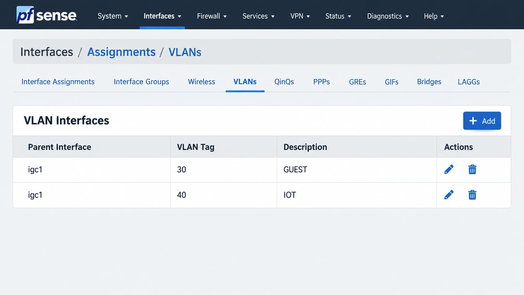
Illustration: The VLAN list after adding GUEST and IOT on the example parent interface igc1. Use the interface name from your firewall.
Assign and Address Both VLANs
Layer 3On the Interface Assignments tab, add each new VLAN from Available Network Ports. Open its new OPT interface, enable it, rename it GUEST or IOT, and set a static IPv4 address. Apply changes. The interface name in firewall rule tabs should now match the intended network. Avoid selecting an upstream gateway on these internal interfaces.
Interfaces > Assignments > Interface assignments > add VLAN 30 and VLAN 40Interfaces > GUEST: Enable; Static IPv4 10.30.0.1/24Interfaces > IOT: Enable; Static IPv4 10.40.0.1/24❯ What to Verify
GUEST and IOT are enabled, use the intended subnets, and appear as rule tabs.Provide DHCP on Each Network
AddressingUnder Services > DHCP Server, enable a DHCPv4 scope for each new interface and enter a range inside its subnet but outside statically assigned addresses. pfSense releases may use the Kea or older ISC backend; confirm the active backend and use the interface’s DHCP page rather than assuming identical options. If clients use the firewall as DNS, leave the DNS server field at the value recommended for your setup or explicitly supply that interface’s gateway address.
Services > DHCP Server > GUEST: 10.30.0.100-10.30.0.199Services > DHCP Server > IOT: 10.40.0.100-10.40.0.199❯ What to Verify
A test client on each VLAN receives an address, matching gateway,and usable DNS settings from the correct scope.Build Explicit Inbound VLAN Rules
FirewallOn Firewall > Aliases, create a network alias such as LOCAL_NETS containing every internal subnet to protect, including GUEST, IOT, management, servers, and any other routed local networks. On the GUEST tab, put a DNS pass rule to the firewall interface address above a block rule to LOCAL_NETS, then an Internet pass rule below it. Repeat on IOT with only the destinations and ports its devices truly require. pfSense interface rules inspect traffic entering that interface, top to bottom. Do not add a broad pass rule above the local-network block.
Firewall > Rules > GUEST (IPv4; top to bottom):1. Pass UDP/TCP 53, GUEST net -> GUEST address (if using firewall DNS)2. Block any, GUEST net -> LOCAL_NETS (log during pilot)3. Pass approved outbound traffic, GUEST net -> any
Firewall > Rules > IOT: repeat with only approved DNS and outbound needs
❯ What to Verify
The protected subnets are blocked before the outbound pass rule.Only intended DNS and Internet destinations are reachable.Test Isolation and Internet Access
ValidationFrom a guest test device, verify its DHCP lease, reach the firewall DNS service and one public site, then attempt to reach a management or server address that should be blocked. Repeat from IoT. Review Status > System Logs > Firewall for the expected block rule, and investigate unexpected passes. Test both wired and wireless clients if both are in scope; a failed DHCP lease often means a tagging problem rather than a firewall-rule problem.
Expected: Guest -> Internet allowedExpected: Guest -> management/server subnet blockedExpected: IoT -> only documented services allowedCheck: Status > System Logs > Firewall❯ What to Verify
Positive and negative tests pass from both VLANs, and the matching ruleis identifiable in the firewall log.Save the Working Configuration
CloseoutDocument the switch and AP tag mappings, subnet plan, DHCP scopes, and rule intent. Download an encrypted configuration backup from Diagnostics > Backup & Restore after the pilot works. Keep the backup password outside the configuration file and test recovery in a separate lab before relying on it.
Record: parent NIC | switch trunk | VLAN IDs | subnets | DHCP ranges | rule order | positive/negative test results | backup location❯ What to Verify
The deployed segmentation and recovery path are documented for future changes.